Category: Projects Related to Palm OS PDAs
A microcontroller for Palm m100
Published on: 2021-07-17
After I built the LiPo Palm m100, I knew that I wanted to hook up a microcontroller to it. A relatively small one is the "D1 mini". Of course, there are even smaller ones, but this one comes with a USB controller, making it easy to program even when it is already wired up.
Since the space in the m100 was already used by the charging components for the LiPo battery, the microcontroller and all required modules were placed outside the m100.
Needed for this modification:
- D1 mini microcontroller
- TTL ↔ RS232 converter
- 5V Voltage regulator (optional)
- 0.96" OLED Screen (optional)
- Three mini switches (optional)
The first attempt was to connect the TX and RX wires of the m100 directly to the D1 mini. This wasn’t a good idea since the output voltage of the RX/TX lines is nearly 12V, which can easily damage the D1 mini. I was extremely lucky that the controller survived.
After connecting the wires directly, I hooked up a small oscilloscope and saw the 12V problem:
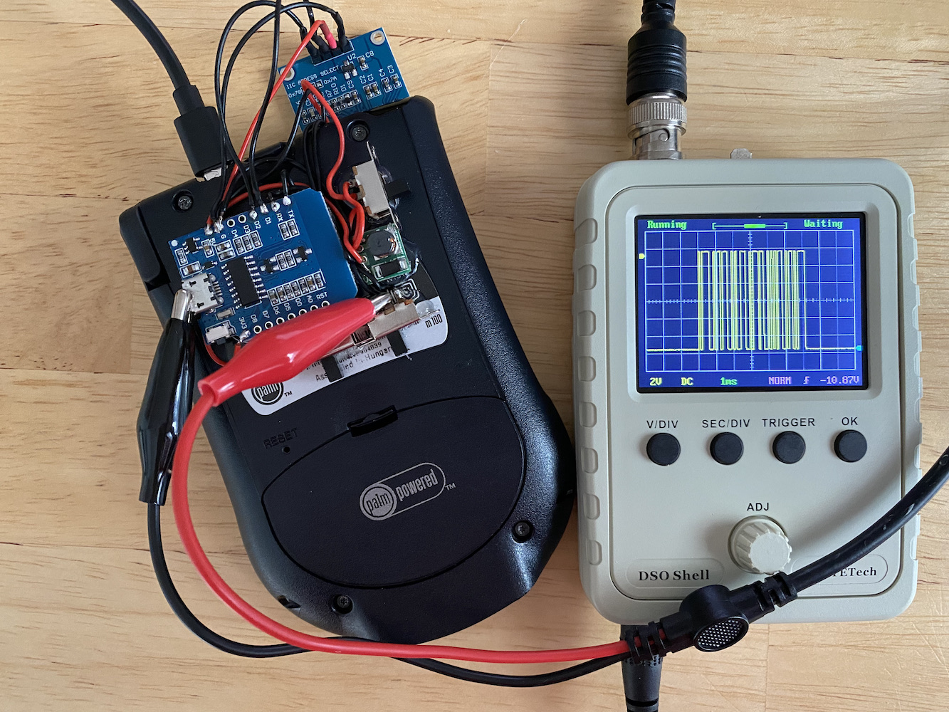
To fix this problem, a TTL ↔ RS232 converter was used, which converted the 12V to around 3.3V, which the D1 mini can handle.
A second “mistake” was that I connected the RX line of the m100 to the TX line of the D1 mini and vice versa. Since the RX and TX lines of the D1 mini are also used for USB communication and uploading files, I soldered a switch to disable the wires from the m100 while uploading a sketch to the D1 mini. I was able to upload sketches again, but debugging the sketch via the Serial Monitor of the Arduino IDE was still not possible. The solution was to use SoftwareSerial, which made the RX/TX switches unnecessary.
Serial communication can be used with any GPIO pin of the D1 mini. Since a 0.96” OLED screen was used for simply outputting some text, pin D4 is used as the RX line and D3 as the TX line. D2 is connected to the “Serial Clock Line” (SCL) of the display and D1 to the “Serial Data Line” (SDA).
The LDO used for powering the Palm m100 can only provide up to 200mA, which can be critical when also powering the D1 mini and the OLED display. This is why a 5V voltage regulator is used to convert the battery voltage to 5V. The regulator has a wide input range from 0.8V to 5V and always outputs 5V, which is then converted to 3.3V through the voltage regulator of the D1 mini. The setup is very power inefficient because two regulators are used. It is better to convert the battery with a 1A LDO voltage directly to 3.3V and feed this voltage to the Palm and the D1 mini. This will be done in the near future. (But for prototyping, it is good enough with two regulators.)
A third switch can be used for powering the 5V regulator because the D1 mini will not be used the whole time.
Of course, everything needs to be connected to the same ground wire.
Next, the D1 mini needs some care. It should receive data from the Palm and display it on the attached OLED display.
But not much is needed, so the following script for the D1 mini is quite simple:
All the script does is wait for data on the "SoftwareSerial" port and send the data as a String to the display.
And this is the complete setup:
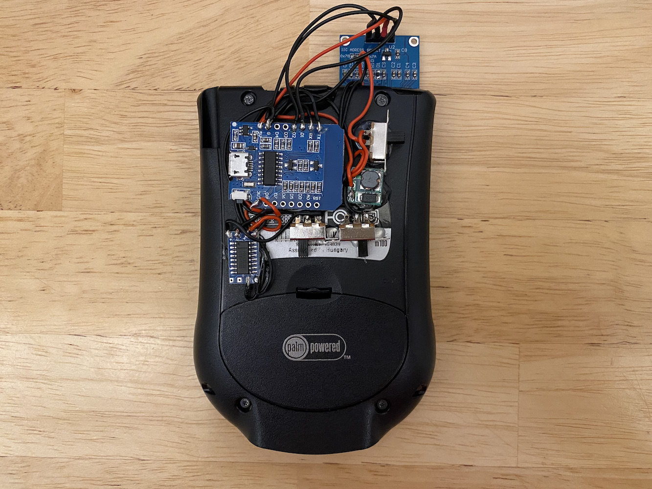
(Still with the wrong connection: RX needs to be switched with pin "D4" and TX with pin "D3"!)
… in action: