Introduction
The Palm m100 or m105 are PDAs that typically run with two AAA batteries. Each battery has a voltage of 1.5V. In this case, the batteries are connected in series, so the total voltage is 3V. A boost regulator transforms these 3V into 3.3V, which then powers nearly the whole system. Initially, it was planned to connect a microcontroller to the Palm and power it with a rechargeable battery. So, why not power the whole Palm with a rechargeable battery? The idea of integrating the microcontroller was discarded relatively quickly to avoid making everything too complicated. Therefore, only the idea of supplying the Palm with a lithium polymer battery remained.
Technical Details
A lithium polymer battery supplies up to 4.2V when fully charged. When it is empty and should not be damaged, it only supplies 3.6V. So, given a 3.6V - 4.2V input voltage range (compared to the 2.0 - 3.0V range of two AAA batteries). Additionally, a boost regulator regulates the usual 3V to 3.3V, and an analog-digital converter measures the input voltage, which then gets displayed on a battery status bar in Palm OS.
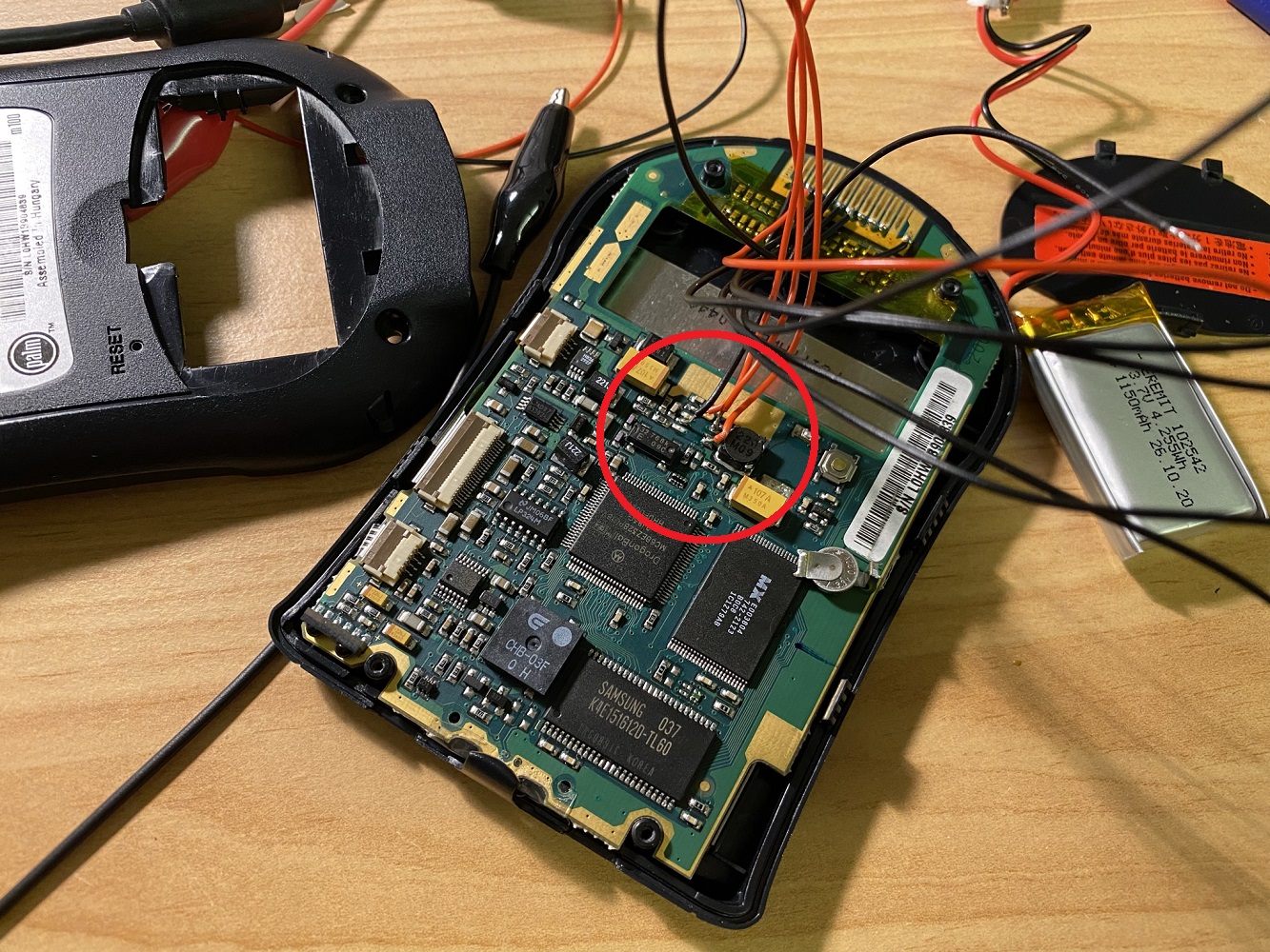
First, it was necessary to locate the boost regulator. Some kind Reddit users helped me with this, so I soon knew that this was the voltage regulator:
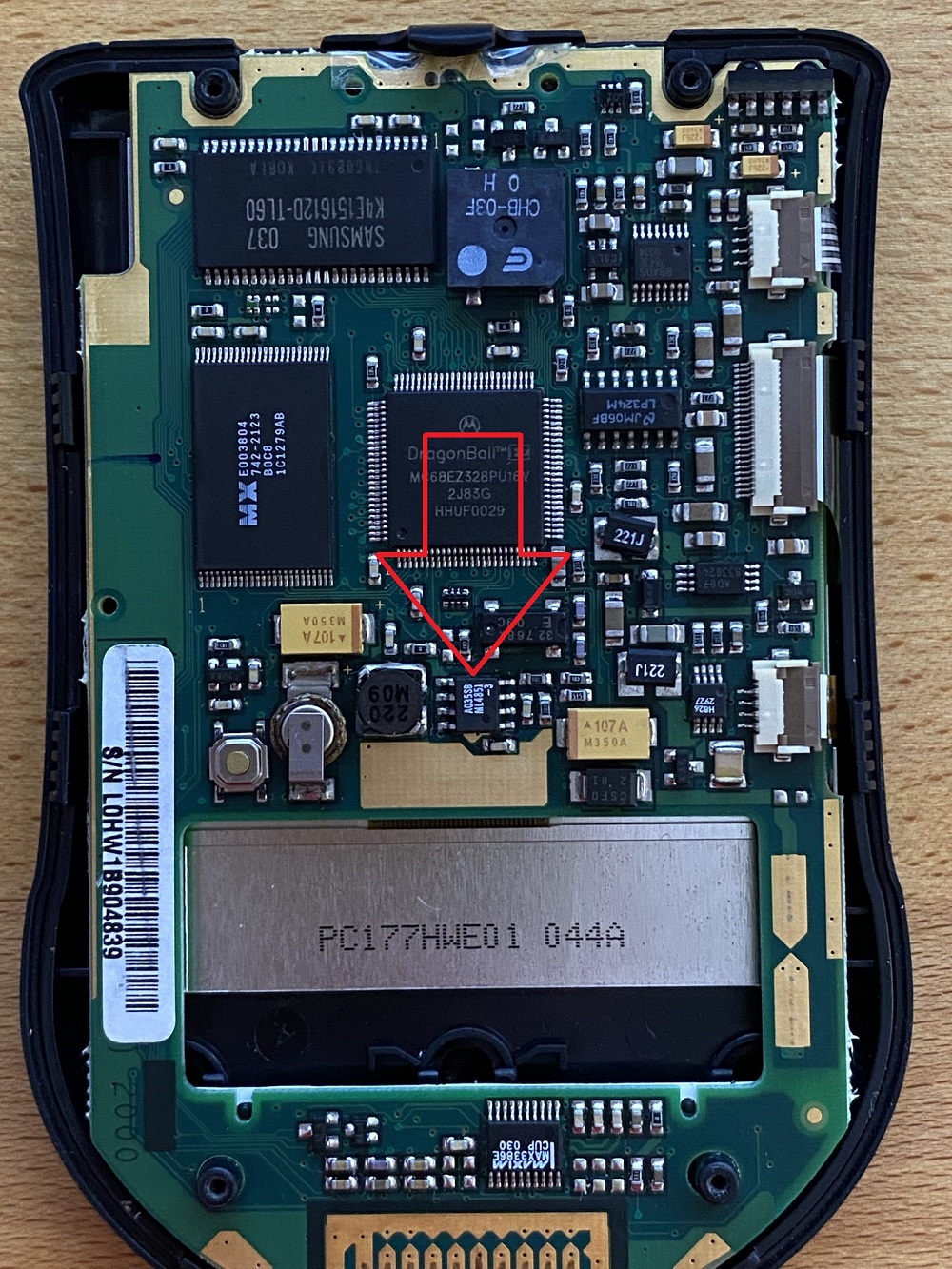
A ML4851-3, which has a maximum input voltage of 3V. Using it to regulate the 4.2V/3.6V of the LiPo was not an option. A Reddit user suggested using an LDO (Low dropout regulator). So, the idea was to use an LDO to regulate the 4.2V to 3.3V and bypass the boost regulator. Since I only had a 3V LDO and the components used are fine with a 0.3V voltage difference, I replaced the boost regulator with the 3V LDO. Fortunately, the Motorola CPU used can, according to the data sheet, operate with a voltage deviation of +/- 0.3V. 3.3V is the "standard" voltage, so 3V from the LDO is still within the limit.
The second step was to measure the voltage of the different pins of the original boost regulator. There were 3.3V on the "Rest" pin and on Vout. GND, of course, was ground and Vin needed the 3V input voltage.
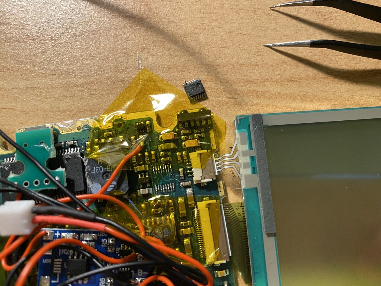
The third step was to desolder the old voltage regulator. Since the new LDO (a LDK120M30R) was quite small, I used a PCB, which extended the pins to a 2.54mm grid dimension. According to the data sheet of the LDO, it needed two ceramic 1µF capacitors to do its job. The old Vin and Rest connection points, where the old voltage regulator was placed, were wired to the "out" pin of the LDO. Also, the old input pin, where the AAA batteries were placed, was connected to the LDO since I was not sure if there wasn't something between the battery and the old voltage regulator that needed to be supplied with voltage.
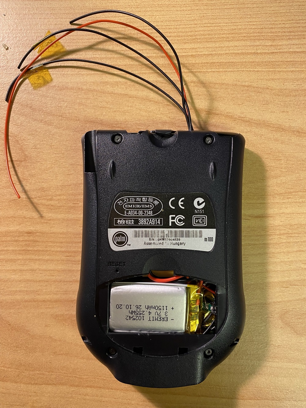
The fourth step was to handle the battery status bar in Palm OS. When 3V were applied to the input of the Palm, the battery status bar was full and with only 2V it was empty. So a voltage divider should divide the voltage of the LiPo battery to the required range. The voltage was read by an ADS7843, which is a touch screen controller with four analog-digital converters. "IN3" (pin 7) of the ADS7843 was responsible for the battery status bar. When it was shortened to ground, the battery status bar showed an empty graph, which verified that pin 7 was the correct pin. The ADC only requires 0.1 µA. So, I used a 1MOhm and a 1.5MOhm resistor for the voltage divider, which provides 2.52V on the 1.5MOhm resistor when the LiPo battery has a voltage of 4.2V (fully charged) and 2.16V when the LiPo battery is empty (3.6V). This means that when the battery status bar shows a half-empty status, the LiPo is full, and when the battery status bar is empty, the LiPo battery is empty, too. In order to get the voltage divider working, I needed to desolder the touch controller, bend pin 7 up, and solder the touch controller back in place. Afterward, I soldered a wire to pin 7 and the voltage divider and secured it with some hot glue.
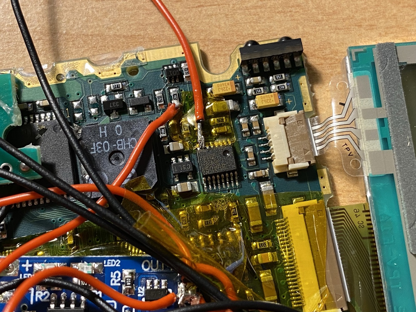
(The red wire next to resistor "103" was only soldered in for testing purposes and was removed later.)
The last step, after some testing, was to put everything together. For charging the LiPo battery, I'm using a "TP4056" charging module. With a standalone micro-USB port on a PCB, I was a bit more flexible for placing the port:
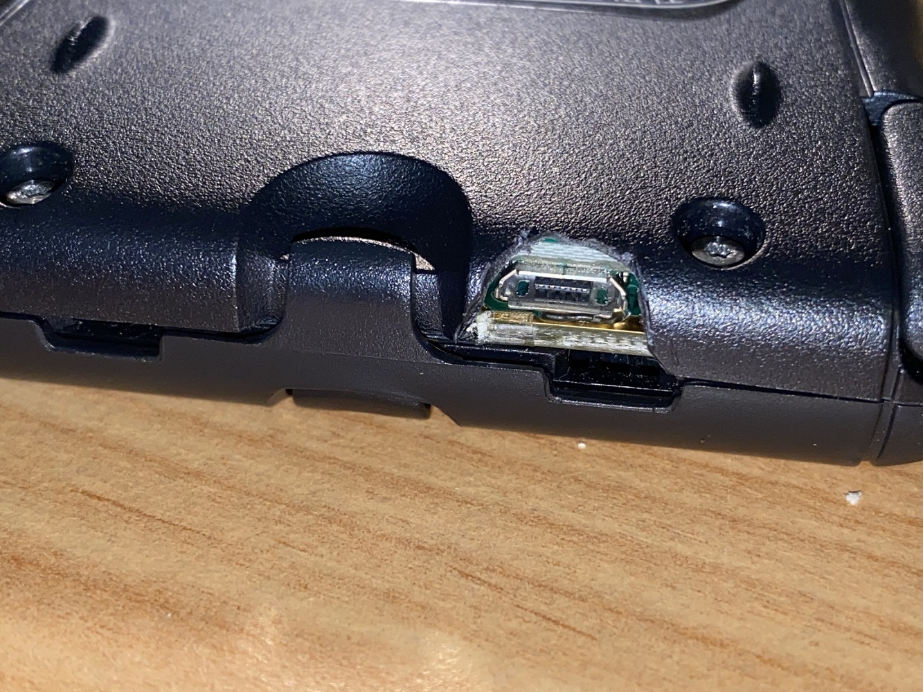
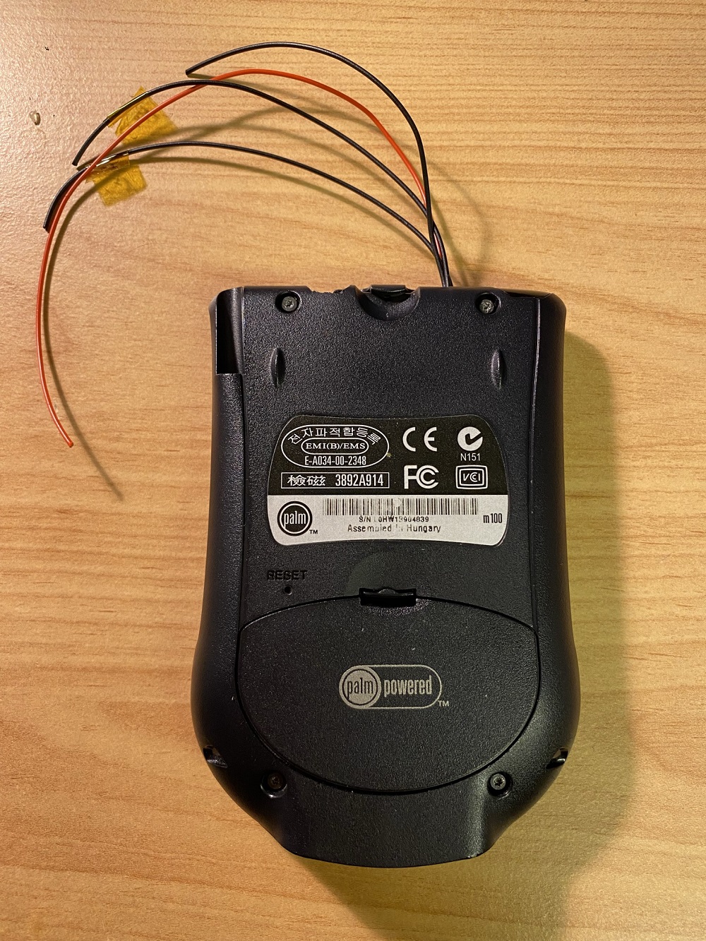
After some trimming of the Palm m100 housing, isolating everything with kapton tape, and soldering some wires to the TX and RX pins of the docking connector for some future projects, everything was ready to be put back together. Luckily, everything fitted in the m100 housing:
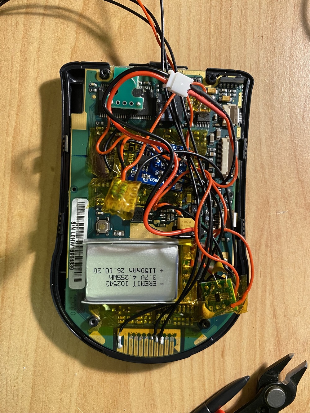
When the backlight is on and a stress test was running, the complete system consumes only 72mA, which is just fine for the LDO, which can provide up to 200mA. So everything looked fine. But unfortunately, after one week of standby for the Palm m100, the LiPo battery was completely empty. Hopefully, I'm able to publish an update with a fix soon. So far, I want to thank the Discord users "dmitrygr" and "jercos" for their help and support.
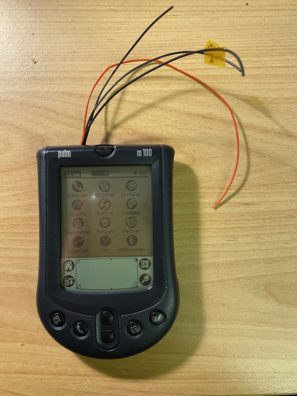
And this is the final modification (for now):